
 简体中文
 英語
A 6 mm nylon tube that pulls straight out of a connector at 0.8 MPa is rarely a defective fitting. In the field reports that come back to us, the cause is almost always one of three things: the tube was cut with a dull blade, it was pushed in a few millimetres short of the collet, or the fitting was sized for a 4 mm line that later ran at close to double the flow.
The short version: choose the fitting family by how often the joint has to be opened, size it by tube outside diameter and port thread, and accept or reject the installation by insertion depth and a pull test — not by feel.
Rule of thumb: the working pressure of a joint is set by its weakest element — tube, seal or body — not by the number printed on the valve upstream.
What a Pneumatic Fitting Actually Has to Do
Every fitting in a compressed-air circuit performs four jobs at the same time, and a product that is good at three of them will still fail in service:
- Join — connect tube to tube, tube to thread, or tube to a component port without changing the direction of the run unless that is the point.
- Seal — hold pressure against the tube wall, usually through an elastomer ring rather than metal-to-metal contact.
- Hold — resist pull-out and vibration loosening. This is a mechanical function performed by a collet or a clamp, not by the seal.
- Pass flow — keep the internal bore close to the tube bore, because every reduction in diameter costs pressure.
Most circuits are designed around valves and cylinders, yet the fitting is normally the cheapest item on the bill of materials and the most common source of a slow leak. That mismatch is why a five-minute selection check pays for itself: a fitting that is one size too small does not leak, it just quietly converts your carefully calculated actuator speed into something slower.
Four Fitting Families and Where Each One Belongs
Fittings are usually grouped by how they connect, because the connection method is what decides assembly time, serviceability and the way the joint will eventually fail.
| Family | How it connects | Typical use | What usually goes wrong |
|---|---|---|---|
| Push-in (one-touch) | Tube pushed past a collet; released by pressing the ring | OEM machines, mixed tube runs, fast assembly | Tube not seated past the collet; teeth dull after repeated re-insertion |
| Thread-to-tube | Male or female thread into a port, push-in or ferrule on the tube side | Valve ports, cylinder ports, manifolds | Wrong thread standard (BSP versus NPT) or over-torque cracking the port |
| Tube-to-tube union and reducer | Two push-in ends, equal or reducing bore | Splicing, panel runs, joining coil lengths | Outside-diameter tolerance differences between tube suppliers |
| Barbed with hose clamp | Hose pushed over a barb and clamped | Coolant, vacuum, larger bore, high vibration | Clamp tension and hose hardening; not repeatable |
| Function fittings | Body plus a mechanism: flow control, bulkhead, tee, Y, check | Speed adjustment, wall crossings, branching | Set point drifts when there is no lock nut |
The three shapes that cover most of a machine's tube runs are the straight male connector, the male elbow and the speed control valve. If you are standardising a platform, qualify those three first and let the rest follow.
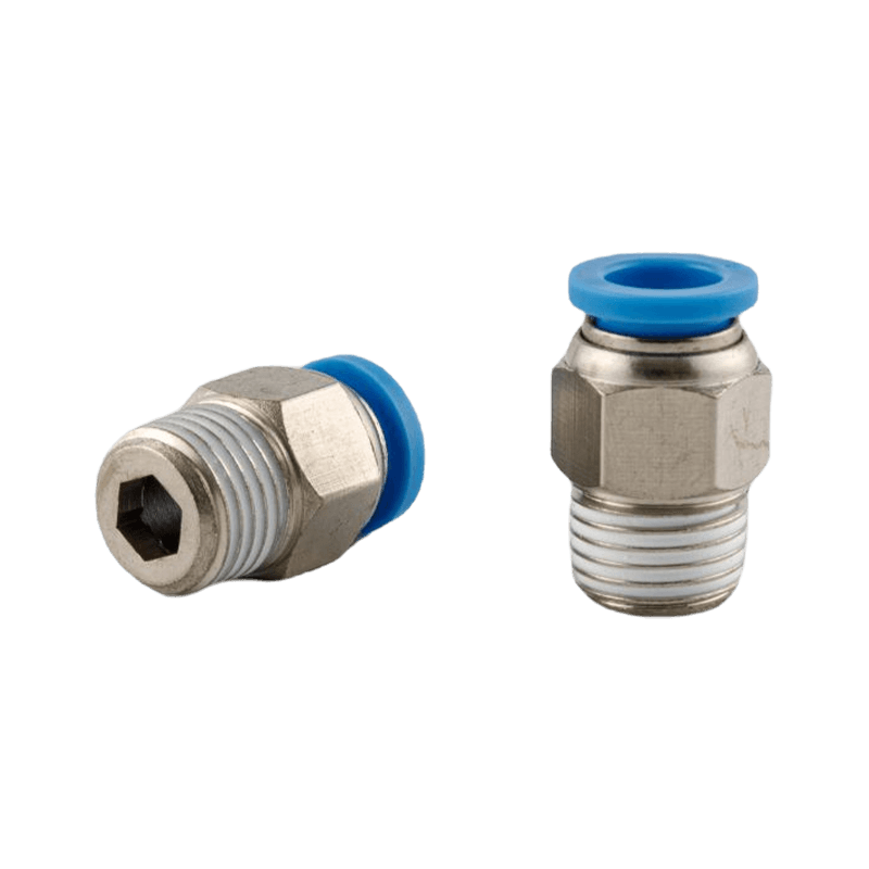 GPC Series Straight Hexagon Socket Head Male ConnectorsStraight push-in fitting for port entry, with 0–1.0 MPa working pressure and hose/thread options for standardising tube runs.View Product →
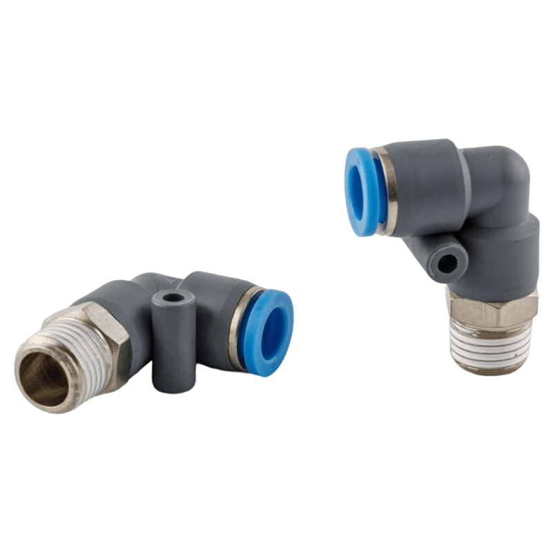 Male Elbow 90° Pneumatic Push-In FittingsNinety-degree push-to-connect elbow for turns at the valve, available in multiple tube and thread sizes up to 16 mm and PT1/2.View Product →
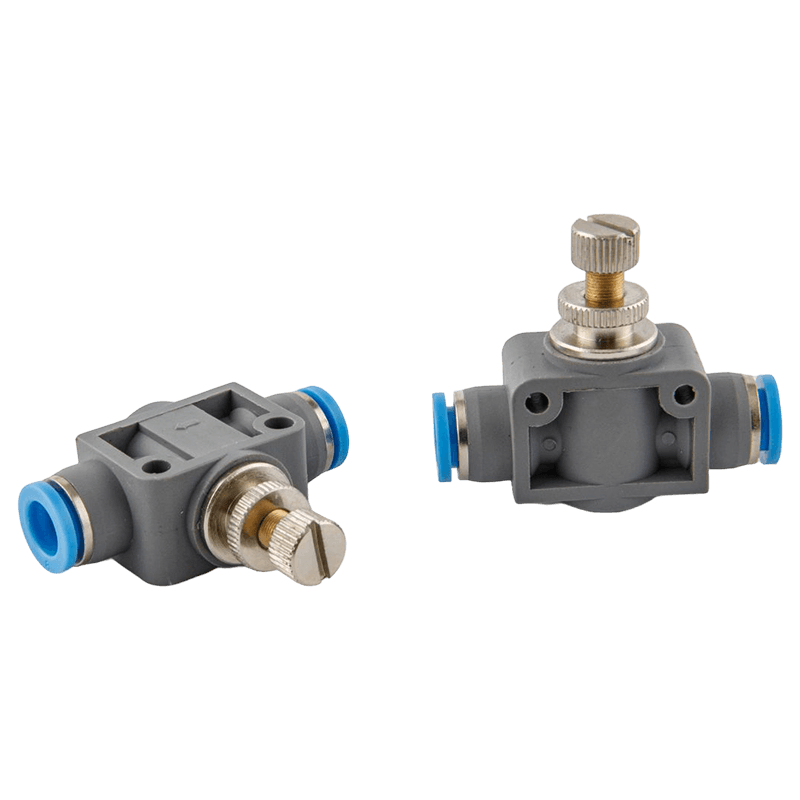 Speed Control Pneumatic Push-In ValvesPush-in speed control valve for slowing one cylinder stroke, with 0–1.0 MPa working pressure and GPSA models for secure hose connections.View Product →
Straight connector for port entry, elbow where the run turns at the valve, speed control where the cylinder has to be slowed on one stroke only.
Inside a Push-In Fitting: Five Parts, Five Failure Points
A one-touch fitting is a small mechanism, and each of its five functional elements fails in a different way. Knowing which part does what shortens troubleshooting considerably — the sealing and gripping sequence inside a push-in fitting is worth thirty seconds of study before the next leak hunt.
- Tube. Outside diameter tolerance and surface finish are part of the seal. A scratch along the tube becomes a leak path straight past the O-ring.
- Release ring. Pressing it retracts the collet. Prising it with pliers is the fastest way to destroy the grip.
- Collet. Hardened teeth bite the tube wall. Each re-insertion dulls them slightly, which is why a joint that held for a year may not hold after the third maintenance stop.
- O-ring. This is the actual seal. Heat hardening, incompatible oil and nicked edges account for most leaks that appear weeks after commissioning.
- Body and thread. The thread carries the mechanical load. Sealant belongs on the thread only, never in the bore.
Sizing: The Numbers That Decide Fit and Flow
Two numbers do most of the work: tube outside diameter and port thread. Everything else — body material, seal compound, release style — is a refinement of those two.
| Tube OD | Common port thread | Flow area index (4 mm = 100) | Typical duty |
|---|---|---|---|
| 4 mm | M5, G1/8 | 100 | Sensor lines, mini cylinders |
| 6 mm | G1/8, G1/4 | 225 | Light actuators, packaging machines |
| 8 mm | G1/4, G3/8 | 400 | General automation |
| 10 mm | G3/8, G1/2 | 625 | Larger cylinders, short mains |
| 12 mm | G1/2 | 900 | High-flow branch lines |
Area is geometric: doubling the bore quadruples the cross-section. Real flow also depends on fitting bore, bend radius and the number of elbows in the run.
Pressure needs the same care. Plastic-body push-in fittings are commonly published at roughly 0–1.0 MPa working pressure and around 0–60 °C with polyurethane tube — but the tube, not the body, is usually the limiting element, so confirm the figure on the datasheet for the exact tube you are using rather than the one on the catalogue cover.
Matching the Fitting to the Application
Once the size is fixed, the remaining choice is about how the joint behaves rather than how it fits. Two families can both be correct on paper and still behave very differently over five years of production.
Indicative comparison on a five-point scale for the same nominal bore; the profile shifts with media, temperature and the number of maintenance cycles.
- If the joint is opened more than twice a year, push-in wins on labour even at a higher unit price.
- If the line runs hot, is subject to water hammer, or carries coolant and swarf, threaded and ferrule connections are more forgiving.
- For washdown or outdoor exposure, specify nickel-plated brass or 304/316 stainless; the plastic release ring is often the first part to age under UV.
- Where a run crosses a panel or a guard, use a bulkhead fitting rather than drilling a clearance hole — the tube will otherwise chafe through at the edge.
Material selection is where manufacturer experience actually shows. A body machined to a high concentricity holds the O-ring square to the tube, which is the difference between a fitting that seals at first assembly and one that seals after ten thousand cycles. That discipline is part of our manufacturing background, and it matters more in fittings than in almost any other pneumatic component because the tolerances are small and the consequences are visible.
Installation and Leak Testing in Five Steps
The majority of "bad fittings" we are asked about turn out to be installation issues. The procedure below is short enough to put on a work instruction card.
- Cut square with a tube cutter, not side cutters. Deburr the inner edge and blow the offcut out of the line.
- Mark the insertion depth on the tube with a marker, or use the depth ring moulded on the body.
- Push in firmly until the tube stops, then pull back with a light, steady force of roughly 5–10 N to seat the collet teeth.
- Tighten the thread to the port specification. Use the correct sealant or a captive O-ring, and keep both clear of the first two threads and the bore.
- Pressure-ramp and test: 0.3 MPa first, then working pressure. Soap solution on every joint, and a 24-hour standing test for lines that cannot be accessed during production.
One habit prevents most repeat failures: never re-use a tube end that has already been gripped. Cut 10 mm off and start again. The teeth leave marks, and those marks are where the next leak begins.
Common Failures and What They Usually Mean
| Symptom | Most likely cause | What to do |
|---|---|---|
| Tube separates under pressure | Not inserted past the collet, worn teeth, or undersized tube OD | Re-cut square, insert to the stop, pull-test; replace the fitting if teeth are dull |
| Bubble at the thread | Sealant missing, sealant in the bore, or a port cracked by over-torque | Clean the port, reseal on the thread only, torque to specification |
| Leak appears after weeks of service | O-ring hardened by heat or swollen by incompatible oil | Change the seal compound, for example NBR to FKM or EPDM |
| Flow lower than calculated | Fitting bore smaller than the tube bore, or an elbow where a swept bend was needed | Use a full-flow or one-size-up fitting; replace sharp elbows with swept versions |
| Body cracked at the port | Mismatched thread standard (BSP, NPT, metric) or excessive torque | Confirm the thread standard before tightening, not after |
FAQ: Pneumatic Fittings
Q1. What is the difference between a pneumatic fitting and a pneumatic connector?
In practice they are the same thing. "Fitting" is the general term for any component that joins tube, pipe or a port; "connector" usually refers to the straight male or female version of it.
Q2. What size pneumatic fitting do I need for a 6 mm tube?
The tube side is fixed at 6 mm outside diameter. The other end depends on the port: M5 or G1/8 for small valves, G1/4 for most cylinders. Always measure the tube OD, not the inner diameter.
Q3. Can push-in fittings be reused?
The fitting usually can, the tube end usually cannot. The collet teeth leave marks that become leak paths, so cut 10 mm off the tube before re-inserting. After several cycles, replace the fitting.
Q4. What pressure can pneumatic push-in fittings handle?
Most plastic-body types are published around 0–1.0 MPa, but the tube and the seal compound normally set the real limit. Check the datasheet for the exact tube, temperature and medium in your line.
Q5. How do I tell whether my thread is BSP or NPT?
BSP threads have a rounded crest and a 55-degree angle; NPT threads are tapered with a sharper 60-degree profile. A thread gauge is the only reliable check — forcing the wrong one cracks the port.
Q6. Why does my pneumatic fitting leak at the tube?
Almost always one of three things: the tube is not fully inserted, the cut end is not square, or the O-ring has hardened. Re-cut, re-seat, and if it still leaks, replace the seal or the fitting.
If you are standardising fittings across a machine platform, the practical next step is to fix one tube series, one thread standard and one sealing method, then qualify two suppliers against the same pull test and the same 24-hour standing pressure check. That single test tells you more about a pneumatic fitting than any catalogue table.